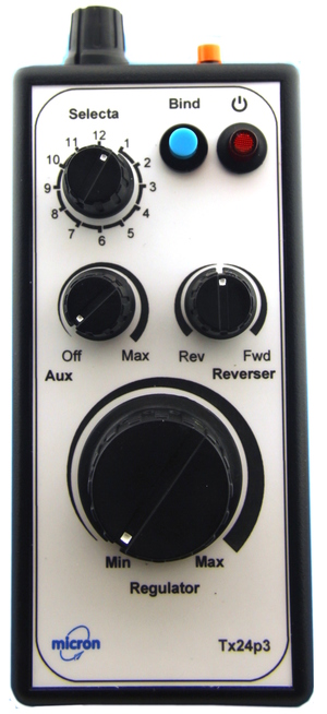
Tx24p3 is a hand-held wireless transmitter
intended to control live-steam locomotives or battery electric
locomotives with the speed controller set to low-off operation.
It has rotary controls for low-off regulator, centre-off reverser,
inertia and auxiliary (e.g blower or gas) plus a 12-way loco
selection switch and 2 push buttons for functions such as steam whistle,
lighting or couplers.
Tx24p3 can be used for MR001a and Deltang receiver programming using the
reverser control to step through programming levels.
Programming details for each receiver may be accessed from the web page
for the receiver.
Technology
Tx24p3 uses the 2.4GHz band which requires no frequency
channel control and is very resilient against interference.
All radio frequency components are contained on the internal
Tx2 module.
There are no user adjustable parts on this module and it should not
be modified.
Tx24p3 is compatible with all DSM2 receivers; this includes all
Deltang receivers.
Any number of receivers can be bound to your Tx24v2 but only up
to twelve, bound to different Selecta positions, should
normally be switched on at a time to operate them independently.
Range is suitable for indoors and small outdoor sites; the outdoor
free-air range to a Deltang receiver is at least 50m.
Range indoors is affected by building construction materials,
furniture, people and receiver installation.
Control knob movement and push button actions are transmitted
as separate R/C channels which must match the receiver configuration:
| Regulator: | channel 1 |
| Selecta: | channel 2 |
| Reverser: | channel 3 |
| Push Button (S2): | channel 4 |
| Bind Button: | channel 5 |
| Aux: | channel 7 |
The top panel Inertia control is implemented in the transmitter software
and does not control a R/C channel.
Battery
Tx24p3 uses a PP3 9V battery, preferably Alkaline or NiMH / Lithium rechargeable.
The maximum working voltage of the internal electronics module is 10V
and there is a protection diode wired in series with the battery lead.
This allows the battery voltage to be up to 10.7V.
If the battery voltage is above this value, the internal
regulator will shut down and the transmitter will not operate.
To replace the battery:
- Make sure that the power on/off button is off (up) before)
adding or removing a battery.
- Remove the lid at the bottom rear of the case by sliding it downwards.
When Tx24p3 is new this will require a bit of effort to slide it past the
retaning 'click'. The image at the right shows the case rear with the
battery lid removed.
- Remove the battery from the compartment and pull the battery clip
off the terminals. Replace the clip on the new battery which will only
fit one way round.
TAKE CARE, if force is needed, the connector is probably the wrong way
round.
- Replace the battery cover by sliding it up from the bottom making
sure that the retaining tab goes under the case rear. The battery is
held in place with a piece of foam attached to the cover and you will
feel some resistance as the cover is pushed down onto the battery.
On / Off Push Button
Tx24p3 has an illuminated push-button latching on/off switch.
The LED lights continuously when the transmitter is on and flashes
when Tx24p3 is in bind mode (see below).
It is best to switch the transmitter on before the receiver.
If a receiver is switched on with Tx24p3 off, it is likely
to enter bind mode with rapid flashing of the LED on the
receiver board. If you did not intend to bind, switch the
receiver off, then switch Tx24p3 on followed by the receiver.
Selecta
Selecta is a 12-way rotary switch with positions matching those of a clock;
it controls R/C channel 2.
Selecta allows 12 locos to brought in and out of service without touching
them (requires Selecta enabled receivers - e.g. MR001).
Regulator Control
The regulator is a 300° rotary control and uses R/C channel 1.
Inertia/Momentum Control
The Inertia control is on the top panel.
Inertia 'dampens' or slows down changes to Regulator (R/C channel 1).
The Regulator knob sets a 'target' and Inertia changes the transmitted
value slowly until it reachs that target.
The Tx24p3 LED flickers while a change is in progress.
To stop quickly Regulator and Inertia must be in the 'off' position.
Inertia is off when turned fully to the left.
Bind Button
Note: holding the bind button for longer than 20 seconds
will result in strange things happening (see Calibration).
If a receiver has not previously been bound, it has to be 'paired' with
the transmitter. Binding is only required once per receiver.
- Put your receiver into bind mode. Consult your receiver
documentation for how to put it into bind mode; if a Deltang Rx4
or Rx6 receiver, switch it on and wait for the LED to flash fast).
- Press and hold the Bind push-button on the transmitter.
- Switch the transmitter on by pushing the Power button and then
release the Bind button.
- Binding is complete when the receiver LED stops flashing.
Push Buttons
The top panel S2 button and the Bind button may be used to
control auxiliary functions such as a steam whistle, lighting or servo
actuated couplers.
The controls affect the following R/C channels:
| S2 button: | chan 4 | up = mid, pressed = low |
| Bind button: | chan 5 | up = high, pressed = low |
where low, mid and high are used in receiver programming instructions
and are equivalent to servo pulse widths of 1ms, 1.5ms and 2ms.
Receiver Programming
Tx24p3 can be used to program Micron MR001a and Deltang receivers.
You need to refer to the receiver's programming instructions for details of
the available functions and the programming sequence to modify the functions.
Please contact Micron if a receiver programming table looks daunting
and we will send you specific programming instructions for
the function you want to change.
A receiver must have been bound to Tx24p3 to program it.
All of these receivers have a common method of entering programming mode
and modifying the program data.
There are 2 methods of getting a receiver into programming mode:
- place the controls for R/C channels 2 and 4 at the extreme positions and then switch receiver on, or
- switch receiver on and enter the morse code SOS using the Bind button (R/C channel 5)
Method 1 works for all receivers, method 2 works only for Micron MR001a
and Deltang Rx6 types.
Method 1 (chan 2 and 4)
- switch the transmitter on
- place the Reverser control in the centre position
- rotate Selecta to position 12
- push and hold down the top panel S2 button
- switch on a receiver which has been bound to this transmitter; the
receiver LED should flash fast within a few seconds.
- release S2 and rotate Selecta to position 6
- the receiver LED will flash once, pause and repeat - this
is called a '1-flash' and corresponds to the 1st level of the
first row in the receiver programming table
Method 2 (SOS)
- switch the Tx24p3 on and then the receiver, receiver LED must be lit
- centre the Reverser control
- wait at least 5 seconds without touching any transmitter control
- tap out the morse SOS (... --- …) on the Bind button where:
- a dot is a short press of less than 0.7 second
- a dash is a long press of about 2 seconds
- pauses between dots or dashes is about 1 second
- if the SOS is accepted, the receiver LED will flash once, pause and repeat
- if the SOS was not accepted go back to step 3
To enter a receiver program sequence
The Tx24p3 Reverser control is used to enter the value for each level
of the program sequence, the receiver LED flashes to show the digit value.
For example, the sequence to set the Deltang Rx60 output P3 to on/off
latching and operated by the bind button is 3 3 2 5 1.
Decoding this sequence gives:
| Level | Value | Explanation |
|---|
| 1 | 3 | Programming table menu 3 |
| 2 | 3 | Rx60 output P3 |
| 3 | 2 | on/off latching mode |
| 4 | 5 | R/C channel 5 = Bind button |
| 5 | 1 | start at 0V, toggle between 0V and 3.3V each
time the Bind button is pressed (R/C channel 5 goes low) |
As each programming level is entered, the receiver flashes to show the value,
pauses and then repeats the flash count.
The initial 1-flash after entering programming mode is for menu 1, level 1
- the left most column of the top row of the programming table.
- rotate the Reverser control fully CCW (reverse) and return
to centre to increment the number of receiver LED flashes for
the current program level
- each level has a maximum value, the flash count wraps to 1
- if the current flash count is 4 and you need 2, you have to
increment to the max, increment again to get to 1 and
then again to get to 2
- rotate the Reverser contol fully CW (forward) and return
to centre to accept the current flash count and move on
to the next level in the programming sequence
- when all programming levels have been entered, the receiver LED
will light solid and the receiver will exit programming mode
The receiver LED will show rapid flashing while the Reverser control
is at the full CCW or CW position and returns to slow flashing (or
light continuously if at the end of a sequence)
when the Reverser control is returned to the centre.
The new program sequence is stored only when the end of the sequence
is reached.
If you lose your position in the program sequence, turn the receiver
off and start again.
Repeat the above for each program function that you wish to alter.
For example, to set the Deltang Rx65 ESC output to respond to full range
throttle on channel 1 and
direction control on channel 3, the program sequence is 1,1,2,1,3.
('REV' means rotate the Reverser control fully reverse and back to centre;
'FWD' means rotate the Reverser control fully forward and back to centre)
- Enter programming mode
- Rx LED displays 1-flash, FWD to accept
- Rx LED displays 1-flash, FWD to accept
- If Rx LED does not display 2-flash, REV until it does, then FWD
- If Rx LED does not display 1-flash, REV until it does, then FWD
- If Rx LED does not display 3-flash, REV until it does, then FWD
- Rx LED lights solid
Calibration
All ready-to-use transmitters are calibrated as the final manufacturing step.
This sets the throttle control centre position and normally
only needs to be done once.
If you suspect that the throttle control is not operating correctly or
you have replaced any of the internal components (e.g. throttle potentiometer),
your transmitter may need calibration.
If the bind button has been inadvertently held down for longer than 20 seconds,
the previously stored calibration data will have been overwritten and
you could find that the throttle control behaves strangely.
To perform calibration:
- centre the Regulator knob (white mark pointing to top of case)
- rotate Selecta to position 6
- centre the Reverser knob
- centre the Aux knob (white mark pointing to top of case)
- switch the Tx on
- within 60 seconds, press and hold down the Bind button
- after 20 seconds, the Tx LED will:
- go off for 2 seconds
- come on for 3 seconds
- go off for 2 seconds
- come on for 3 seconds
- go off and stay off
- Release the Bind button, the Tx LED will stay on
The transmitter controls are now calibrated.