Eliminate worry about dirty track, stalls, shorts
and all the frustrations of track power.
Battery power and radio control – the future of model railways.
Radio control (R/C) operation of model railways offers considerable
advantages over
conventional methods, either direct voltage control or DCC.
Like DCC, each R/C model is controlled from within the model itself,
so there are no problems running more than one train on a track.
But, R/C allows battery operation eliminating any worries about dirty
tracks, getting stuck on insulated turnout frogs, etc.
R/C trains can operate alongside track
powered locos, either direct control or DCC.
There is no need to section the track, R/C provides true 'cab control'
so you always have full control over your train.
Some R/C controllers can handle up to 12 locos, switching 'active' control
between each of them. Non-active locos can be configured to either continue
at the last setting or stop.
Compared to the complexity involved in trying to achieve the same level of
operation from conventional wiring, the installation of a R/C
battery operated locomotive is relatively simple.
The on-board components consist of a radio receiver, usually with built-in
speed controller, batteries and motor connected as shown on the right.
A switch is needed to isolate the battery when the loco is not in use
and some method of connecting to a charger is also required - both can
be achieved simply with micro plugs/sockets.
A fuse in the battery positive lead is recommended to protect the battery
in case of inadvertent shorts while working on the loco.
for motor and battery: the red and black wires go to the battery
and the yellow or white wires go to the motor.
Our range of receivers covers all scales
and gauges; from N to SM32, Gauge 1 and beyond with motor currents from
0.5A to 6A. If your motor needs more than 6A, a receiver and separate speed
controller can be used.
Although most ready-to-run locos have 12V motors to suit powered
rail layouts, many trains do not need this voltage. Slow speed operation
(e.g narrow gauge and shunting) works well with 6V or less; even main-line
locos rarely use more than 9V. These voltages are easily provided from
single (3.7V) or double cell (7.4V)
Lithium Polymer batteries.
Multiple cell LiPo batteries require a balancing charger and multi-wire
charge lead (e.g. 4 wires for a 3 cell battery).
A simpler solution for > 4V, easier to install and charge,
is to use a single cell LiPo with a
voltage booster module.
Receiver Options (top)
| MR601
| 2.7V-13V receiver, up to 1.2A motor current
|
| MR603 |
4.5V-20V, 3A receiver, suitable for larger locos (e.g. O Gauge, SM32) |
| MR001 |
5 servo and 2 on/off outputs (e.g. for lighting) but no built-in
speed controller. Use with servos for live steam or a
high current ESC for > 6A |
The receivers have short wire aerials. Some are also available with
an extended aerial for use in totally enclosed metal bodied locos.
All receivers have multiple auxiliary outputs for controlling lights,
coupling actuators, sound modules or whatever on-board function your
imagination wants to implement.
The receivers contain extensive programmable features so that you
can implement exactly the model control you need.
Each receiver is available with several 'variants' which provide a selection of
the programmable features appropriate for a typical use.
When selecting a receiver you must ensure that:
- the battery voltage when fully charged does not exceed the maximum
allowed for the chosen receiver - Rx4x
receivers have a maximum working voltage of 6V;
MR603 can operate on 20V.
- the battery voltage when nearing discharge is above the minimum
voltage for the receiver.
- the motor current when stalled must not exceed the maximum allowed
for the chosen receiver - see the receiver specification;
completely enclosing the receiver (e.g. in foam) will reduce the
current capacity, it is always a good idea to allow for air circulation
Choosing a receiver:
| battery
| motor type |
receiver |
| 3V..6V: single LiPo cell, 3-4 NiMH cells |
small motor - e.g. 7mm - 10mm coreless |
MR601 |
3V..6V: single LiPo cell, 3-4 NiMH cells |
larger motor - e.g. RE280, RE360;
these low voltage motors have a high start/sall current |
MR601 (250Hz PWM recommended) |
3V..13V: 1-3 LiPo cells, 3-8 NiMH cells |
any motor up to 1.2A start/stall current |
MR601 |
4.5V..20V: 2-5 LiPo cells, 4-14 NiMH cells |
any motor up to 3A start/stall current |
MR603 |
When installing a miniature receiver in your model, you must ensure that no
force or stress is applied to the circuit board. Miniaturisation requires
thin materials which must naturally be handled gently.
Most of the receivers are supplied as bare boards and care must be taken
to avoid shorting the circuit board tracks. A heat shrink sleeve cover
will provde protection and this is available as a no-cost option on
many of the receivers we stock.
Also, the motor output must not be shorted.
Receiver Outputs
All receivers have several auxiliary outputs in addition to the motor
controller. These can be used for controlling lights, sound cards, smoke
generators, couplers, etc.
Use of these outputs is highly variable as it depends on what additional
behaviour you want to build into your model.
Please contact Micron if you want to discuss the options.
Receiver outputs are labelled 'H', 'P' and 'F' to denote their capability:
- H
- H-Bridge Reversible Speed Controller
Most model rail receivers have at least one reversible speed
controller - the exception is MR001 which is for
live steam or, with an external ESC, (very) large scale locos.
- P
- low-current voltage source
This is a direct connection to the receiver microprocessor: off is 0V
and on is 3.3V. It is commonly used for switching LEDs for lighting.
The maximum current is limited by the CPU capability:
8mA for most Rx4x
and 20mA for MR603,
With care, a P output may be used to control external circuits (e.g.
sound module) with higher voltages by switching to ground via a
series 4k7 ohm resistor (the max current still applies)
- F
- high-current switch
This is a FET switch with an open-drain which allows it to control
high voltage (> 3.3V) external circuits with up to 2A current.
When the switch is off, the output pad floats (not connected to either
negative or positive); when on, the output is connected to negative.
If a receiver has no F outputs (or not enough) but you need to switch
a load current
greater then 20mA, an external
FET switch can be used to convert a P to a F.
Transmitters / Controllers (top)
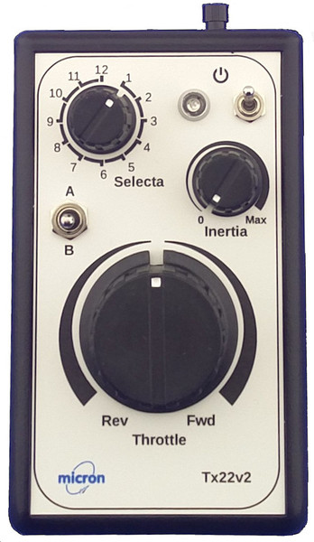
Tx22v2
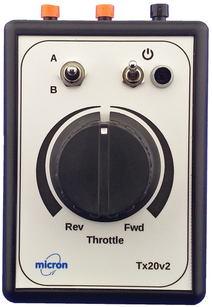
Tx20v2
We have a range of compatible hand-held transmitter controllers from simple,
single loco to multi-train units.
All are pocket sized and available with forward / reverse on
one knob or full-range throttle and separate direction control.
We can also build bespoke controllers with knobs,
switches, push buttons to match your needs.
Many transmitters can be used simultaneously without frequency control or
crystals.
For this to work, every receiver needs to be paired with one transmitter in
a process called binding.
During binding, the transmitter's unique ID (GUID) is given to the receiver.
The receiver then only obeys that transmitter.
A receiver needs binding only once. When the receiver is switched on,
it searches for its bound transmitter - which is why the transmitter
should be switched on first.
The transmitter can share its GUID with any number of receivers.
One transmitter can control any number of locomotives, but they all receive the
same signals so you normally only have one loco switched on at a time.
Some of the Micron transmitters have the 'Selecta' feature which is
used to select a loco to control.
When used with a Selecta enabled receiver (variant -22), the position
of the Selecta switch is stored by the receiver during bind.
This allows up to 12 locos to be switched on at the same time
and the Selecta switch controls which loco is currently active.
The Selecta feature is supported in most receivers, but must be enabled
before use.
All Micron controllers and receivers operate on 2.4GHz using the
popular Spektrum DSM2/DSMX protocols. This means that they are compatible with
a wide range of other R/C equipment.
| Tx20v2 |
A simple, single loco controller with large knob for throttle control,
a centre-sprung 3-way switch that can be used for direction control
or for lighting, sound, etc. and 2 push buttons that can be used
to actuate any of the receiver auxiliary outputs. |
| Tx22v2 |
A controller for up to 12 locos using the 'Selecta' system.
Receivers respond to commands to enable and
disable control - a 'disabled' receiver can be configured to
stop the motor or continue at the current setting.
|
The Tx21v2 and Tx22v2 transmitters
have an 'inertia' control which sets the loco acceleration and
deceleration behaviour. Inertia is implemented in the transmitter to
ensure compatibility with all model rail receivers.
Many receivers also have a built-in
inertia function which may be enabled by programming the receiver.
Batteries (top)
Whilst it is possible to run locos with non rechargeable batteries,
it is more economical to use rechargeable batteries.
On-board batteries can be NiMH, LiIon or LiPo. LiPo and LiPo provide
the best size/capacity ratio and ease of installation.
All batteries need careful handling, shorting any type will result
in lots of heat and you MUST use a resettable fuse in the positive
lead as close as possible
to the battery - definitely before the on/off switch and charge socket.
This is to protect your model in the event of a wiring fault.
When selecting a battery for your loco, you need to look for the highest
capacity that will fit into the available space as this will give
the longest run-time before needing a charge.
If shape of the internal space will not allow for a multi-cell battery,
separate cells with interconnecting wires can be used.
Batteries can be charged in the model and LiIon/LiPo can be frequently
topped up when the loco is resting. NiMH is best run until discharged
and then fully charged to avoid voltage depletion (aka 'memory effect').
Most locos do not need the full 12V - 4V or 8V from 1 or 2
LiPo cells is usually sufficient. LiPo cells come
in a wide range of shapes and sizes making it
easy to fit into your loco, tender or wagon.
Installation (top)
First choose the components:
- single loco or multi-loco (Selecta enabled) transmitter
- receiver to suit the loco working voltage and motor stall current
- battery voltage to suit the loco operating style and
capacity/size to fit the available internal space
- 12V for 0 Gauge and smaller, 8V-9V is often sufficient
for shunting locos
- single LiPo cell and voltage booster for locos with restricted
space
- 15V-16V for G Scale and Gauge 1
- wiring harness: on/off switch, charge socket and resettable
to protect the battery
fuse - Micron has a selection of switch modules
which comprise a switch, Molex charge socket and a LED to repeat the
receiver on-board LED
Plan the installation:
- choose location for receiver,
battery (or LiPo cell plus voltage booster),
on/off switch and charge socket
- if a steam loco, an ideal place for the on/off switch is
under a removable dummy coal load
- determine wire lengths between components, route to avoid
moving parts
If the loco has a DCC socket, the actual installation can be easy as
connecting the receiver motor output to the DCC socket motor pins.
Otherwise:
- disconnect the wheel pickups from the motor
- fix the battery in place - protect from movement and any sharp
edges if a metal bodied loco
- fix the receiver in place - a piece of double sided foam tape
(aka servo tape) is usually sufficient
- fix the on/off switch and charge socket in place
- complete the wiring:
- battery to on/off switch, with resettable fuse in battery
positive lead
- on/off switch to receiver
- receiver motor output to motor
You can either wire all components together permanently or use
connectors to allow easy separation of the body from the chassis.
Miniature
1.27mm pitch polarised and non-polarised
connectors are good for the smaller scales (N, OO, 009) and
Molex 2mm pitch connectors are appropriate
for O Gauge, SMT32, Gauge 1, etc.
More complex installations add lighting, sound, smoke control, couplers, ...
The Micron range of receivers is capable of handling it all.
We provide an installation service
if you don't feel up to doing it yourself.
Contact us for details.